Introduction
In this post we will explore sending a cloned IR signal using Arduino.
In previous articles, the method to control modules using a remote and an IR receiver sensor was discussed.
Here, we’ll use an IR emitter LED and an IR receiver.
Equipment
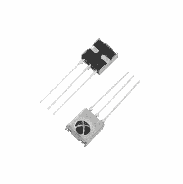
- IR Receiver Sensor (TSOP1738)
- IR Emitter LED
- Resistors (1000 ohms, 220 ohms)
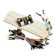
- Arduino UNO
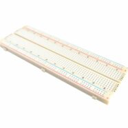
- Breadboard and Connecting Wires
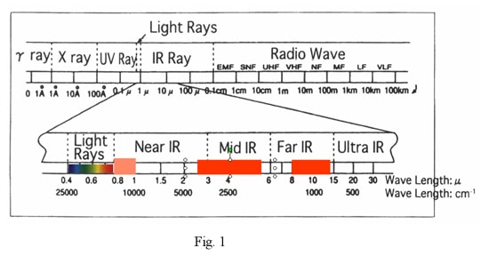
How IR Communication Works
IR stands for Infrared. Infrared has a slightly larger wavelength than visible light. This kind of light cannot be seen by the naked eye. You can appreciate infrared light by turning on your mobile phone’s camera and then aiming it at a TV remote control unit. Pressing a button on the TV remote will make you see the IR light on your mobile phone screen.
IR is widely used for remote communication because of the following characteristics:
- fast propagation
- harmless transmission
- Its rays can be directed to the object being targeted
- It produces signals that are distinguishable from noise through frequency variation
Devices that employ IR technology includes remote controls used for TVs and AC units. These remote units emit IR signals in the 36KHz to 46Khz range while generating a modulated signal.
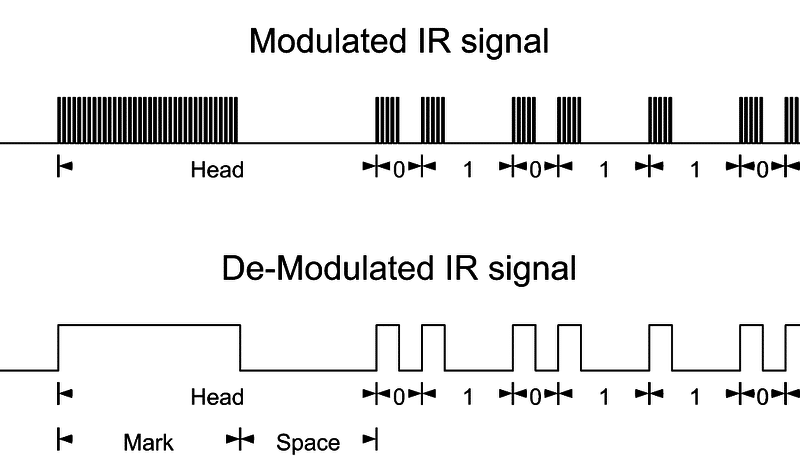
The series of signals are sent with specific on and off times. The corresponding device detects it and is able to determine the correct user command.
More information on IR communication signals can be found in the introduction part of this article by Ardafruit. Adafruit talks about what kind of IR library they use.
Schematic Diagram
Capturing The Signals
If you implement this circuit, you’ll see that any kind of IR signal can be copied and sent to its receiver.
The signal will be sent using an IR emitter LED. Alternatively, in order to receive IR signals, an IR receiver is used. IR codes will be utilized, and these codes will be analyzed by Arduino.
Before starting, ensure that the TSOP1738 sensor is the one being used. This sensor is specially designed for IR communication as it does not emit noisy signals.
After implementing the circuit, make sure that you have the IRremote library installed in your Arduino IDE. If not, go to this link: https://github.com/z3t0/Arduino-IRremote and download the library and install it.
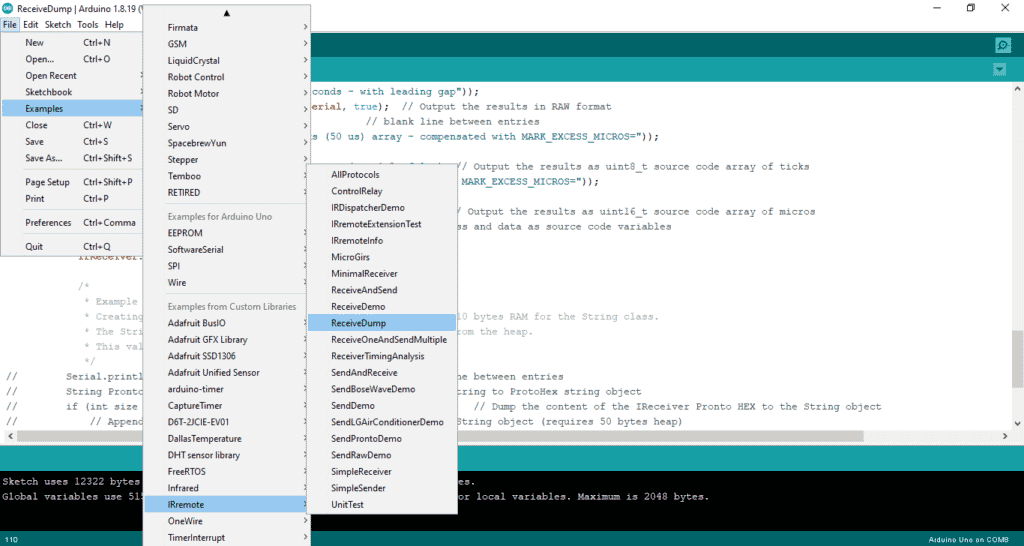
Next, navigate to File > Examples > IRremote > ReceiveDump
And upload the sketch to your Arduino.
Once uploaded, open the Serial Monitor, then use any brand of remote available to aim at the sensor. Then push any button on the remote.
A log should appear similar below, which shows the signal sent with the remote.
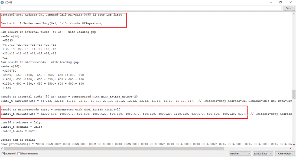
In our example, we’ll use a Sony remote and press the ON button.
Open notepad and record this information. These data will be used to send the signal using Arduino.
Sending Signals
There are two methods of sending the captured IR signals. Function-based and Raw data-based.
Some libraries identify the type of encoding for the Sony TV remote function above. With this, the built-in function sendSony( ) is used with the IR code as a parameter.
This signal can be sent by the following code:
					#include <IRremote.h>
 IRsend irsend;


void setup() {
  Serial.begin(9600);  // put your setup code here, to run once:
}

void loop() {

  IrSender.sendSony(0x1, 0x15, 1);

 delay(5000);
}
The first parameter is the address, the second is the data, and the third is the number of times to send it. This actually came from the information we got from our RecieveDump program:
					Protocol=Sony Address=0x1 Command=0x15 Raw-Data=0x95 12 bits LSB first

Send with: IrSender.sendSony(0x1, 0x15, <numberOfRepeats>);
The code sends the cloned signal at 5-second intervals.
This code, however is limited to SONY encoding and will not work for other encoded signals. For sending various signals using only RAW data, the IRSendRawDemo example code of the IRremote library can be used as a reference.
Navigate to – File > Examples > IRremote > SendRawDemo
Once the file is opened, an array uint16_t rawData[ ] can be seen. The array can be changed with the rawData array received via the serial monitor while running the ReceiveDump program.
uint16_t rawData[25] = {2330,670, 1080,670, 530,670, 1080,620, 580,670, 1080,670, 530,620, 580,620, 1130,620, 530,670, 530,620, 580,620, 530}; // Protocol=Sony Address=0x1 Command=0x15 Raw-Data=0x95 12 bits LSB first
So let’s modify the SendRawDemo to send the Turn ON Sony signal.
					#include <Arduino.h>

#include "PinDefinitionsAndMore.h" //Define macros for input and output pin etc.
#include <IRremote.hpp>

#define USE_SONY

// On the Zero and others we switch explicitly to SerialUSB
#if defined(ARDUINO_ARCH_SAMD)
#define Serial SerialUSB
#endif

void setup() {
    pinMode(LED_BUILTIN, OUTPUT);

    Serial.begin(115200);
#if defined(__AVR_ATmega32U4__) || defined(SERIAL_PORT_USBVIRTUAL) || defined(SERIAL_USB) /*stm32duino*/|| defined(USBCON) /*STM32_stm32*/|| defined(SERIALUSB_PID) || defined(ARDUINO_attiny3217)
    delay(4000); // To be able to connect Serial monitor after reset or power up and before first print out. Do not wait for an attached Serial Monitor!
#endif
    // Just to know which program is running on my Arduino
    Serial.println(F("START " __FILE__ " from " __DATE__ "\r\nUsing library version " VERSION_IRREMOTE));

#if defined(IR_SEND_PIN)
    IrSender.begin(); // Start with IR_SEND_PIN as send pin and enable feedback LED at default feedback LED pin
#else
    IrSender.begin(3, ENABLE_LED_FEEDBACK); // Specify send pin and enable feedback LED at default feedback LED pin
#endif

    Serial.println(F("Ready to send IR signals at pin "  STR(IR_SEND_PIN)));
}


void loop() {

#if !(defined(__AVR_ATtiny25__) || defined(__AVR_ATtiny45__) || defined(__AVR_ATtiny85__))
    /*
     * Send hand crafted data from RAM
     * The values are NOT multiple of 50, but are taken from the NEC timing definitions
     */

    Serial.println(F("Send SONY 16 bit address Address=0x1 Command=0x15 Raw-Data=0x95 with (50 us) tick resolution timing (16 bit array format) "));
    Serial.flush();


    const uint16_t rawData[25] = {2330,620, 1180,620, 530,620, 1180,620, 530,620, 1180,570, 580,670, 530,620, 1130,620, 580,620, 530,620, 580,620, 580};  // Protocol=Sony Address=0x1 Command=0x15 Raw-Data=0x95 12 bits LSB first

    IrSender.sendRaw(rawData, sizeof(rawData) / sizeof(rawData[0]), SONY_KHZ);

    delay(5000);

    IrSender.sendSony(0x1, 0x15, 1); // delay must be greater than 5 ms (RECORD_GAP_MICROS), otherwise the receiver sees it as one long signal

#endif

}
Ensure the red marked spots are changed with the information from data from the serial monitor before and that the code is uploaded to Arduino.
Aim the IR emitter LED at the corresponding device of the remote, and the operation should be witnessed every 5 seconds!
You can download the working Arduino code here.
SHOP THIS PROJECT
-
Sale!

UNO R3 ATmega328P CH340 Development Board – Arduino Compatible with USB Cable
$23.95Original price was: $23.95.$22.95Current price is: $22.95. Add to cart