Want to simplify your circuits or power supply sources to a minimum number of elements? Try using Thevenin and Norton equivalent circuits.
Introduction
In theory, it is known that a linear circuit composed of resistors and power sources can be reduced to a single resistor and power source. This reduction can be useful, especially when simplifying your circuit to make it easier to attach as a module to another circuit. Additionally, power supply sources can be simplified too, using Thevenin or Norton equivalent circuits, so that you can determine the power supply’s source resistance or current limit value.
What is a Thevenin Equivalent Circuit
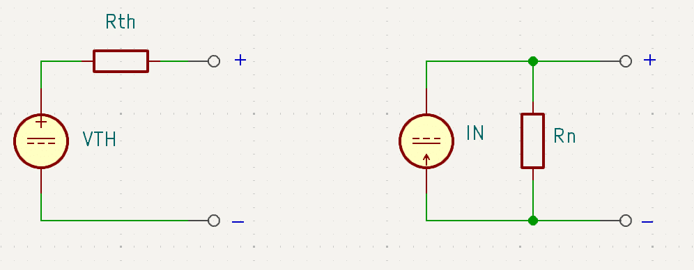
Thevenin’s Theorem states that a linear circuit composed of voltage or current sources and resistances can be combined to form an equivalent circuit composed of only a single voltage source and resistive element in series. The equivalent circuit can be useful for finding its effects when coupled with various loads.
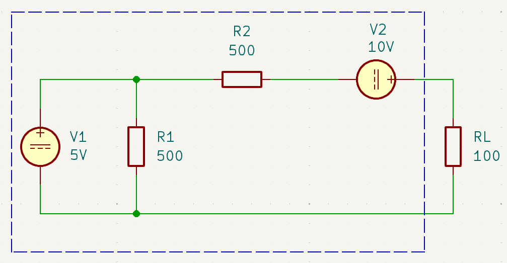
Below is an example of a circuit simplified to a Thevenin Equivalent Circuit (TEC). Notice the circuit has two voltage sources, namely V1 and V2. It also has two resistors, R1 and R2. A load resistance of 100 ohms is attached.
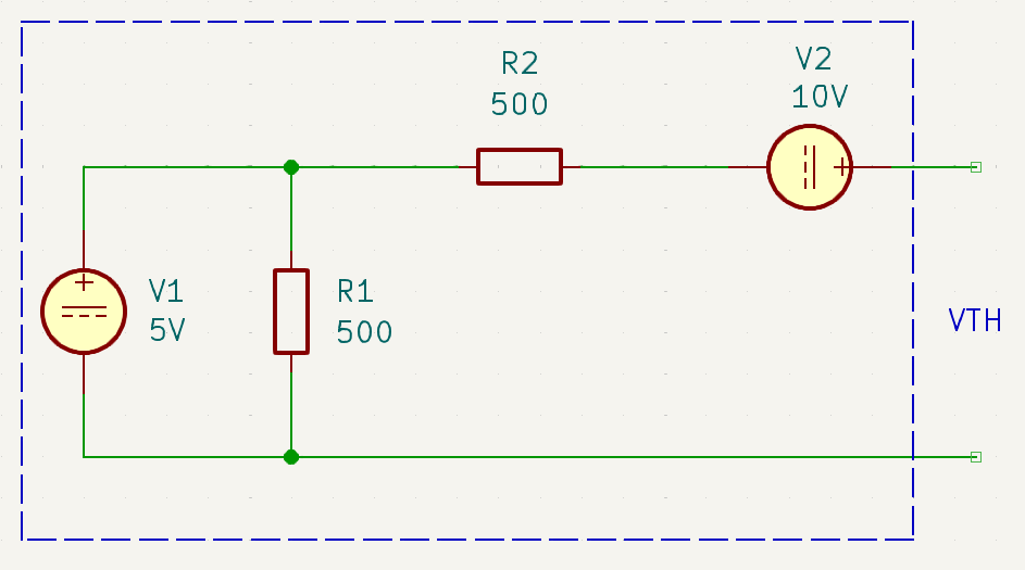
The load is disconnected on the load terminals to find the Thevenin Voltage, VTH.
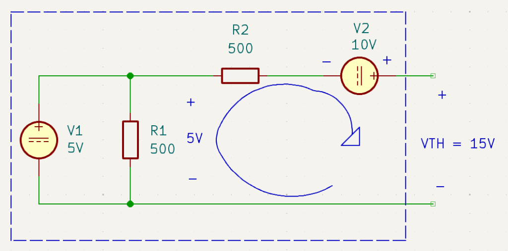
To find the Thevenin voltage, you must find the open-circuit voltage across the load terminals. This value can be found by adding up VR1 (from V1) and V2 through KVL on the loop shown below. Note that since it’s an open circuit, there is ideally no current flow on R2, hence it has zero voltage. The equivalent VTH is 15V.
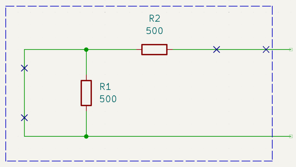
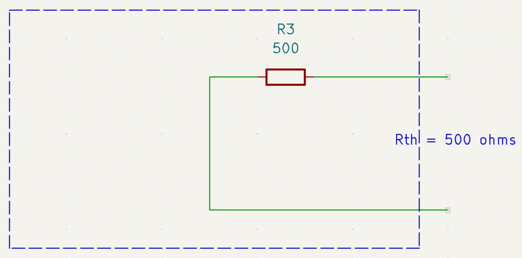
To find Rth, you have to first short out all the voltage sources (or open current sources). Next, find the equivalent resistance on the load terminals.
The value of Rth is found to be 500 ohms.
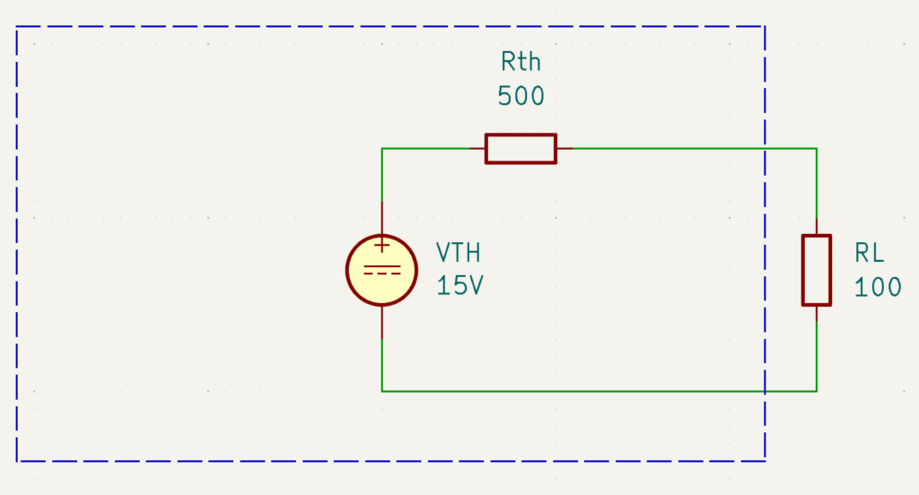
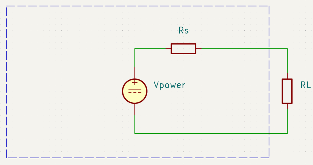
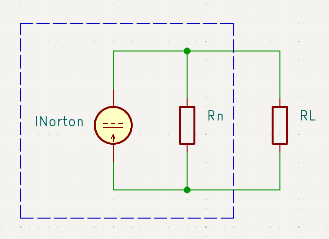
Below is the Thevenin Equivalent Circuit (TEC). You can change the load attached to this circuit to find out its effect. Interestingly, Rth can be likened to Rs (source resistance) from a practical power source model. With these models, you can also optimize your system to have maximum power transfer.
What is a Norton Equivalent Circuit
Norton’s Theorem states that any linear circuit composed of current and voltage sources and resistors can be reduced to a single current source in parallel with a single resistor. The equivalent circuit comes in handy when simplifying your circuits and also has an interesting application in power supply current limiting.
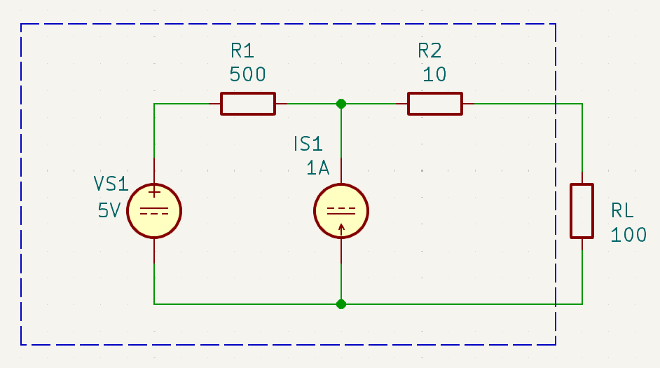
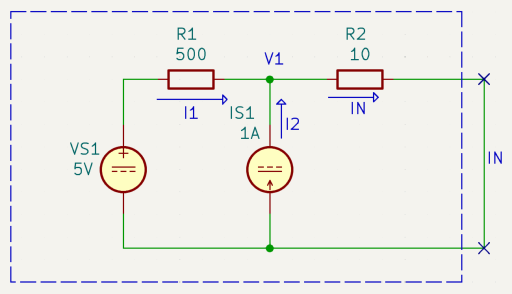
Below is an example circuit that will be converted into a Norton Equivalent Circuit (NEC). It consists of a voltage and a current source and two resistors. A load is attached with a value of 100 ohms.
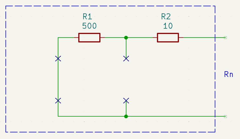
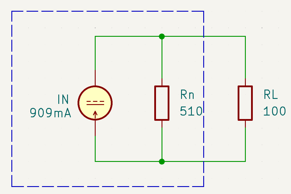
In order to get the Norton resistance, you should take out the load resistor and then open all current sources and short out all voltage sources. The Norton resistance is the resistance as seen from the load. Here, it should be 510 ohms.
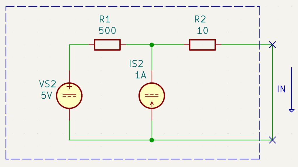
To get the Norton current, you’ll have to short out the load resistor and find the current at that path.
Solving for the Norton current, coming from the V1 node (KCL):
IN = I1 + I2
where I2 = IS1 = 1A
so
IN = I1 + 1A —-> Eq. 1
Another equation coming from R1 is:
I1 = (VS1 – V1)/R1
I1 = (5V – V1)/500 ——> Eq.2
Here is another equation coming from R2:
IN = (V1 – 0V)/R2
IN = V1/R2
IN = V1/10 —–> Eq. 3
Substituting Eq 2 and Eq 3 to equation 1:
IN = I1 + 1A
V1/10 = (5V – V1)/500 + 1A
50V1 = 5V – V1 + 500V
51V1 = 505V
V1 = 9.90V
Then to solve for IN:
IN = V1/R2
IN = 9.09V/10
IN = 909mA
The eqiuvalent NEC is would be:
If you try to vary Rn, you’ll see that you can actually limit the current going to your load, an interesting application for current-limited power sources.
Conclusion
You’ve just learned how to get the Thevenin and Norton equivalent circuits from various examples. Hope you can use them for practical applications on your everyday circuits.