Start learning CAN Bus programming using the STM32 Blue Pill here.
Introduction
Last time, you learned about CAN bus programming in Arduino. This time, you’ll learn how to program CAN bus using the STM32 Blue Pill. The Blue Pill is special because it is equipped with a CAN controller. This means, you’ll only need an additional CAN transceiver to work with the CAN bus.
Circuit Setup
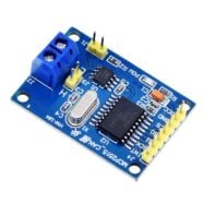
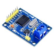
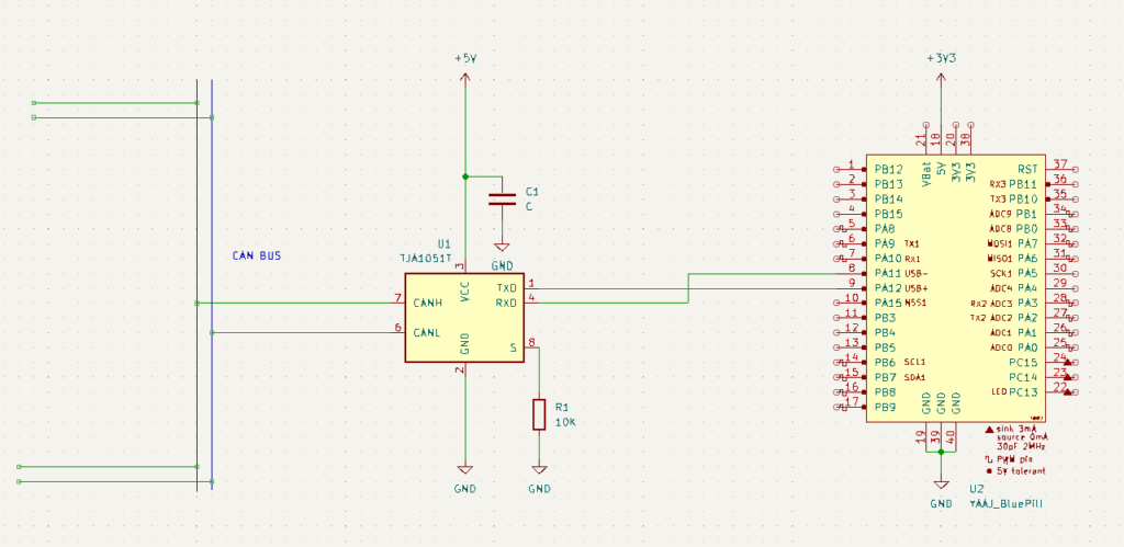
You can use different kinds of CAN transceivers. There is the MCP2551, TJA1050, and SN65HVD230. Here, the TJA1050 will be used as an example.
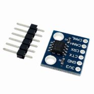
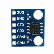
Below, you can see the TJA1050/1 TXD pin connected to PA12, while the RXD pin is connected to PA11 of the Blue Pill. The CANH_ and CAN_L bus lines connect to the CAN bus port of the transceiver. The S pin (or Silent) pin is strapped to ground by a 10k resistor. This means that the transceiver is not in listening mode only.
For the supply, 5V is supplied to the TJA1050, as this transceiver IC needs a 5V supply to operate. The STM32F103C8T6 is supplied with 3.3V. The TXD and RXD lines of the transceiver directly interface to the PA12 and PA11 ports of the Blue Pill, which work with 3.3V logic. Good thing that the PA11 and PA12 ports are 5V-tolerant pins.
Actual Setup
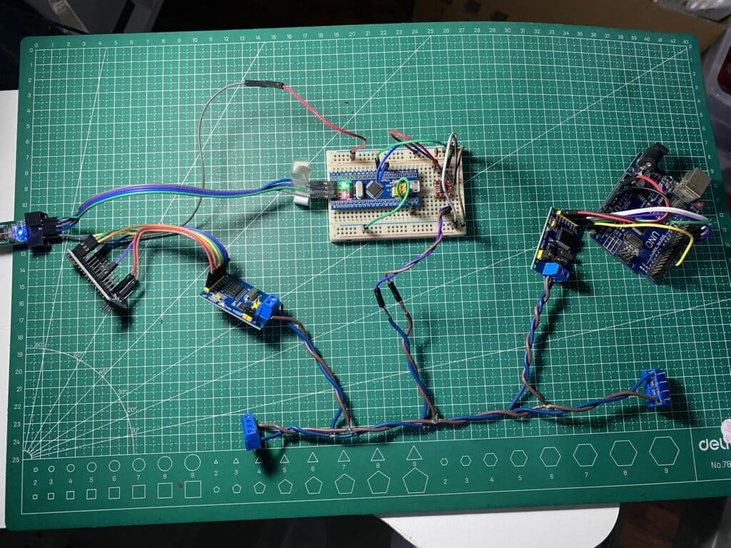
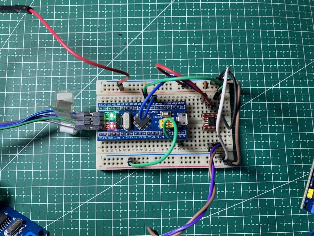
An STM32 Blue Pill with TJA1050 CAN transceiver is added to the previous setup. This circuit connects to the CAN bus. An ST-Link powers the circuit. 3.3V powers the Blue Pill while 5V powers the TJA1050.
Programming
First, activate CAN and choose the correct timing parameters in STM32CubeMX.
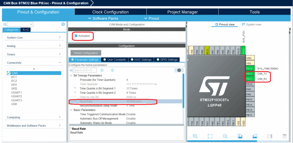
- CAN Clock = 36 MHz
- Bit Time = 2 µs (500 kbps)
- Total Time Quanta (TQ) = 18
- Prescaler = 4
- TimeSeg1 = 13
- TimeSeg2 = 4
- SyncJumpWidth = 1
Note that these settings correspond to an APB1 clock of 36 MHz. The aim is to get a CAN baud rate of 500kbps that is compatible with our previous setup using Arduino boards.
Below is the code for a Blue Pill transmitting a set of data with a CAN ID of 0x321.
					/* USER CODE BEGIN Header */
/**
  ******************************************************************************
  * @file           : main.c
  * @brief          : Main program body
  ******************************************************************************
  * @attention
  *
  * Copyright (c) 2025 STMicroelectronics.
  * All rights reserved.
  *
  * This software is licensed under terms that can be found in the LICENSE file
  * in the root directory of this software component.
  * If no LICENSE file comes with this software, it is provided AS-IS.
  *
  ******************************************************************************
  */
/* USER CODE END Header */
/* Includes ------------------------------------------------------------------*/
#include "main.h"

/* Private includes ----------------------------------------------------------*/
/* USER CODE BEGIN Includes */

/* USER CODE END Includes */

/* Private typedef -----------------------------------------------------------*/
/* USER CODE BEGIN PTD */

/* USER CODE END PTD */

/* Private define ------------------------------------------------------------*/
/* USER CODE BEGIN PD */

/* USER CODE END PD */

/* Private macro -------------------------------------------------------------*/
/* USER CODE BEGIN PM */

/* USER CODE END PM */

/* Private variables ---------------------------------------------------------*/
CAN_HandleTypeDef hcan;

/* USER CODE BEGIN PV */

/* USER CODE END PV */

/* Private function prototypes -----------------------------------------------*/
void SystemClock_Config(void);
static void MX_GPIO_Init(void);
static void MX_CAN_Init(void);
/* USER CODE BEGIN PFP */

/* USER CODE END PFP */

/* Private user code ---------------------------------------------------------*/
/* USER CODE BEGIN 0 */

/* USER CODE END 0 */

/**
  * @brief  The application entry point.
  * @retval int
  */
int main(void)
{

  /* USER CODE BEGIN 1 */

  /* USER CODE END 1 */

  /* MCU Configuration--------------------------------------------------------*/

  /* Reset of all peripherals, Initializes the Flash interface and the Systick. */
  HAL_Init();

  /* USER CODE BEGIN Init */

  /* USER CODE END Init */

  /* Configure the system clock */
  SystemClock_Config();

  /* USER CODE BEGIN SysInit */

  /* USER CODE END SysInit */

  /* Initialize all configured peripherals */
  MX_GPIO_Init();
  MX_CAN_Init();
  /* USER CODE BEGIN 2 */

  // Start CAN peripheral
  HAL_CAN_Start(&hcan);
  // HAL_CAN_ActivateNotification(&hcan, CAN_IT_TX_MAILBOX_EMPTY);

  CAN_TxHeaderTypeDef TxHeader;
  uint8_t TxData[8] = {0xDE, 0xAD, 0xBE, 0xEF, 0x01, 0x02, 0x03, 0x04};
  uint32_t TxMailbox;

  TxHeader.StdId = 0x321;
  TxHeader.ExtId = 0x01; // Not used in standard ID
  TxHeader.IDE = CAN_ID_STD;
  TxHeader.RTR = CAN_RTR_DATA;
  TxHeader.DLC = 8;
  TxHeader.TransmitGlobalTime = DISABLE;
  /* USER CODE END 2 */

  /* Infinite loop */
  /* USER CODE BEGIN WHILE */
  while (1)
  {
	  if(HAL_CAN_AddTxMessage(&hcan, &TxHeader, TxData, &TxMailbox) != HAL_OK)
	  {
		  // Transmission request Error
		  Error_Handler();
	  }

	  printf("Transmitted\r\n");

	  HAL_Delay(1000);
    /* USER CODE END WHILE */

    /* USER CODE BEGIN 3 */
  }
  /* USER CODE END 3 */
}

/**
  * @brief System Clock Configuration
  * @retval None
  */
void SystemClock_Config(void)
{
  RCC_OscInitTypeDef RCC_OscInitStruct = {0};
  RCC_ClkInitTypeDef RCC_ClkInitStruct = {0};

  /** Initializes the RCC Oscillators according to the specified parameters
  * in the RCC_OscInitTypeDef structure.
  */
  RCC_OscInitStruct.OscillatorType = RCC_OSCILLATORTYPE_HSE;
  RCC_OscInitStruct.HSEState = RCC_HSE_ON;
  RCC_OscInitStruct.HSEPredivValue = RCC_HSE_PREDIV_DIV1;
  RCC_OscInitStruct.HSIState = RCC_HSI_ON;
  RCC_OscInitStruct.PLL.PLLState = RCC_PLL_ON;
  RCC_OscInitStruct.PLL.PLLSource = RCC_PLLSOURCE_HSE;
  RCC_OscInitStruct.PLL.PLLMUL = RCC_PLL_MUL9;
  if (HAL_RCC_OscConfig(&RCC_OscInitStruct) != HAL_OK)
  {
    Error_Handler();
  }

  /** Initializes the CPU, AHB and APB buses clocks
  */
  RCC_ClkInitStruct.ClockType = RCC_CLOCKTYPE_HCLK|RCC_CLOCKTYPE_SYSCLK
                              |RCC_CLOCKTYPE_PCLK1|RCC_CLOCKTYPE_PCLK2;
  RCC_ClkInitStruct.SYSCLKSource = RCC_SYSCLKSOURCE_PLLCLK;
  RCC_ClkInitStruct.AHBCLKDivider = RCC_SYSCLK_DIV1;
  RCC_ClkInitStruct.APB1CLKDivider = RCC_HCLK_DIV2;
  RCC_ClkInitStruct.APB2CLKDivider = RCC_HCLK_DIV1;

  if (HAL_RCC_ClockConfig(&RCC_ClkInitStruct, FLASH_LATENCY_2) != HAL_OK)
  {
    Error_Handler();
  }
}

/**
  * @brief CAN Initialization Function
  * @param None
  * @retval None
  */
static void MX_CAN_Init(void)
{

  /* USER CODE BEGIN CAN_Init 0 */

  /* USER CODE END CAN_Init 0 */

  /* USER CODE BEGIN CAN_Init 1 */

  /* USER CODE END CAN_Init 1 */
  hcan.Instance = CAN1;
  hcan.Init.Prescaler = 4;
  hcan.Init.Mode = CAN_MODE_NORMAL;
  hcan.Init.SyncJumpWidth = CAN_SJW_1TQ;
  hcan.Init.TimeSeg1 = CAN_BS1_13TQ;
  hcan.Init.TimeSeg2 = CAN_BS2_4TQ;
  hcan.Init.TimeTriggeredMode = DISABLE;
  hcan.Init.AutoBusOff = DISABLE;
  hcan.Init.AutoWakeUp = DISABLE;
  hcan.Init.AutoRetransmission = DISABLE;
  hcan.Init.ReceiveFifoLocked = DISABLE;
  hcan.Init.TransmitFifoPriority = DISABLE;
  if (HAL_CAN_Init(&hcan) != HAL_OK)
  {
    Error_Handler();
  }
  /* USER CODE BEGIN CAN_Init 2 */

  /* USER CODE END CAN_Init 2 */

}

/**
  * @brief GPIO Initialization Function
  * @param None
  * @retval None
  */
static void MX_GPIO_Init(void)
{
  GPIO_InitTypeDef GPIO_InitStruct = {0};
/* USER CODE BEGIN MX_GPIO_Init_1 */
/* USER CODE END MX_GPIO_Init_1 */

  /* GPIO Ports Clock Enable */
  __HAL_RCC_GPIOC_CLK_ENABLE();
  __HAL_RCC_GPIOD_CLK_ENABLE();
  __HAL_RCC_GPIOA_CLK_ENABLE();

  /*Configure GPIO pin Output Level */
  HAL_GPIO_WritePin(LED_GPIO_Port, LED_Pin, GPIO_PIN_RESET);

  /*Configure GPIO pin : LED_Pin */
  GPIO_InitStruct.Pin = LED_Pin;
  GPIO_InitStruct.Mode = GPIO_MODE_OUTPUT_PP;
  GPIO_InitStruct.Pull = GPIO_NOPULL;
  GPIO_InitStruct.Speed = GPIO_SPEED_FREQ_LOW;
  HAL_GPIO_Init(LED_GPIO_Port, &GPIO_InitStruct);

/* USER CODE BEGIN MX_GPIO_Init_2 */
/* USER CODE END MX_GPIO_Init_2 */
}

/* USER CODE BEGIN 4 */

/* USER CODE END 4 */

/**
  * @brief  This function is executed in case of error occurrence.
  * @retval None
  */
void Error_Handler(void)
{
  /* USER CODE BEGIN Error_Handler_Debug */
  /* User can add his own implementation to report the HAL error return state */
  __disable_irq();
  while (1)
  {
  }
  /* USER CODE END Error_Handler_Debug */
}

#ifdef  USE_FULL_ASSERT
/**
  * @brief  Reports the name of the source file and the source line number
  *         where the assert_param error has occurred.
  * @param  file: pointer to the source file name
  * @param  line: assert_param error line source number
  * @retval None
  */
void assert_failed(uint8_t *file, uint32_t line)
{
  /* USER CODE BEGIN 6 */
  /* User can add his own implementation to report the file name and line number,
     ex: printf("Wrong parameters value: file %s on line %d\r\n", file, line) */
  /* USER CODE END 6 */
}
#endif /* USE_FULL_ASSERT */
You’ll see the CAN module started using HAL_CAN_start(). A CAN transmit header is made composed of TxData[] (the transmit data), StdId (the Identifier), ExtId (not used), IDE = 11-bit Standard CAN, RTR = Data type frame, DCL = 8 (number of data bytes), and Transmit Global time = disabled timestamping.
After that, you can immediately start polling CAN transmit pockets using HAL_CAN_AddTxMessage().
Notice a printf statement was added to know if the CAN successfully transmitted data. To activate printf using SWV (Serial Wire Viewer) on your ST-Link, you can see Debug an STM32 with printf using only an ST-Link.
Below is a demo video of the CAN transmission:
SHOP THIS PROJECT
-
Sale!

MCP2515 Can Bus Module TJA1050 Receiver Board
$19.95Original price was: $19.95.$16.95Current price is: $16.95. Read more