However, FreeCAD made a software overhaul and upgraded to FreeCAD 1.0x. This upgrade made the software more advanced and professional looking. The upgrade fixed some major issues (including the dreaded TNP or Topological Naming Problem), added several features (e.g. Sketcher and Part Design improvements, integrated Assembly workbench, etc.). An upgrade, though, can sometimes make previously working processes have issues. Unfortunately, one of those issues come from the A2Plus assembly workbench having problems with the TPN fix (and other issues as well). With this, some users can be stuck with using the integrated Assembly Workbench.
A2Plus vs. Integrated Assembly Workbench
Here, you’ll see the differences between A2Plus and integrated Assembly as well as the advantages and disadvantages of using each of them.
A2Plus Workbench
Constraint-based assembly – manually apply constraints to place parts in the assembly.
Beginner friendly – easier to work with and has a more visual approach.
Limited parametric and motion animations
Can get unstable with large assemblies
Each part is a separate FreeCAD file that you can edit externally.
Not yet fully stable under FreeCAD 1.0x versions
Integrated Assembly Workbench
Uses the Insert Component function to bring parts in
Uses the Joint function to keep parts together with certain contraints and movements.
You can edit and create parts inside the same document
Integrated within FreeCAD 1.0x, no need to add it as an add-on
Working with Electronic Assemblies Using the Integrated Assembly Workbench
Here is an example demo of working with an electronic assembly using the integrated assembly workbench.
Export your PCB in KiCAD
You can export your board in STEP file format. Select the necessary options you need to export (such as exporting the solder mask, silkscreen, tracks and vias, and others). The Coordinates options may not matter since the built-in assembly takes care of any LCS (Local Coordinate System) internally. You’ll see later that it’s quite easy to merge components using joints instead of referring to an origin.
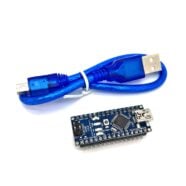
Ready the Step Files you Need to Import for the Assembly
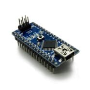
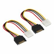
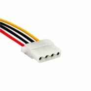
You can ready your 3D step file models to use during assembly. If you’re using KiCAD, you can enter its 3D Model directory to gather and transfer component parts you need to place that are not in your schematic or PCB. If you have an enclosure as a step file, you can also include it here. Otherwise, you can also create your enclosure in FreeCAD so that you can edit it during assembly time.
Open FreeCAD and then Create Separate FreeCAD Documents for each of your Components
To make things easier to work with, each Integrated Assembly components will be placed on separate FreeCAD documents. With this method, you’ll be able to cleanly insert and even edit them (if they were created in FreeCAD) in the assembly workbench. With this, export each of your STEP files into a new FreeCAD document.
Create a FreeCAD Assembly Document
Create a seperate FreeCAD assembly document and then create an assembly using the icon above.
INsert the Component into the Assembly using the Insert Component Icon
You can now insert the components as parts in the assembly by using the Insert Component icon. Note that by default, the first component is a fixed component (meaning it is not able to be moved) and it is marked by a red padlock. You can change this setting later if you want.
Next, you can make a temporary placement by dragging the components anywhere in the drawing area.