Here is a simple audio application that will help you understand the workings of I2S. It involves outputting variable sine wave frequencies to this digital serial protocol.
Introduction
The Intro to I2S blog introduced basic concepts and the connections involved in using I2S. Here, you’ll learn a practical application to understand I2S further. It uses basic sine wave data, controls its frequency, sets a sampling rate, and then outputs serial audio data digitally. You’re on your way to making a variable frequency sine wave generator using I2S.
Components Involved
Check out the previous blog indicating the components to prepare for the I2S tutorial.
Circuit Setup
The basic circuit setup is indicated in the previous blog too to prepare for the I2S series.
Setting up I2S on your BlackPill
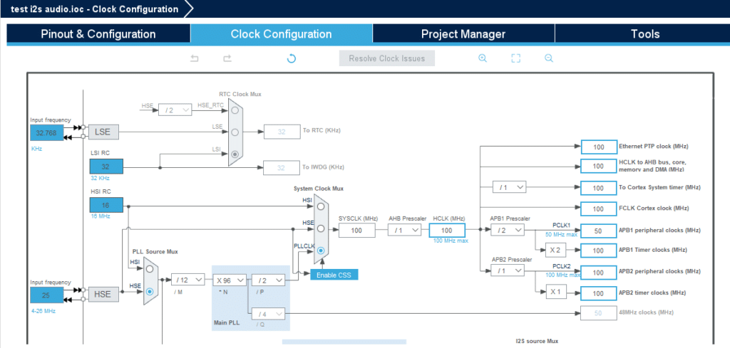
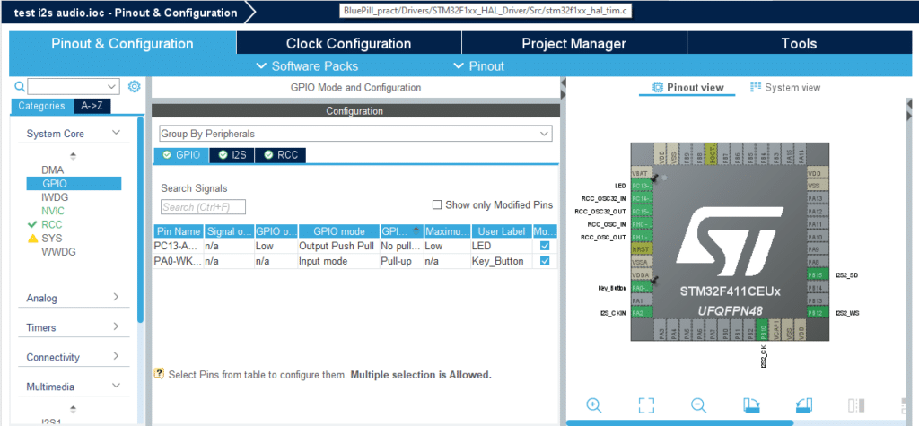
Ensure you’ve gone through STM32Cube IDE tutorial to understand how to use STM32Cube IDE. Also, go through the blog on preparing your BlackPill’s I2S for STM32CubeIDE. Here, the maximum clock rate is used at 100 MHz. The LED, button, and I2S ports are also seen below.
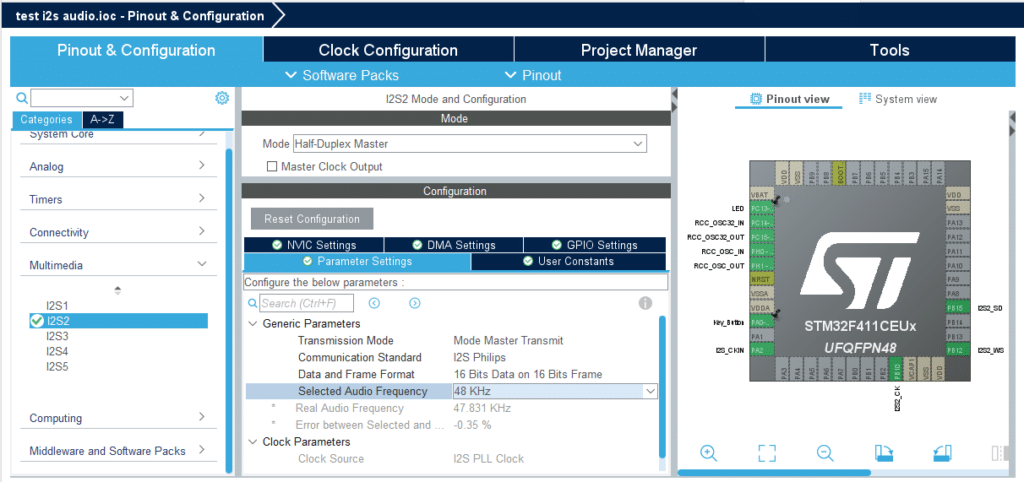
Below, the I2S Peripheral is found under the Multi-Media section of Pinout & Configuration. The Communication Standard used is Philips I2S, with a chosen Audio Frequency of 48KHz. The Data and Frame Format are both 16 bits which will relate to our Sine Table later.
The I2S Peripheral Mode is Half-Duplex Master, indicating a one-way transmission from device to device. The Transmission mode is Master Mode Transmit, meaning the master transmits the audio data while the slave receives this data.
Programming your Basic Sine Wave
To have sine wave data, you need to have a LUT (or a look-up table). There are several online sine wave lookup table generators on the net. It’s okay to use them, especially for fixed-frequency sine waves. However, this project will use a variable frequency sine wave. With this, you may need additional processing.
Credits to Luca, a member of Stack Overflow, a sine wave lookup table and a variable frequency generator can easily be acheived through his code contribution to the site.
					#include "limits.h"
#include "math.h"
					  const int Fs = 48000;       // sample rate (Hz)
  const int LUT_SIZE = 1024;  // lookup table size

  int16_t LUT[LUT_SIZE];      // our sine wave LUT

  for (int i = 0; i < LUT_SIZE; ++i)
  {
      LUT[i] = (int16_t)roundf(SHRT_MAX * sinf(2.0f * M_PI * (float)i / LUT_SIZE));
  }                           // fill LUT with 16 bit sine wave sample values
					  // frequency we want to generate (Hz)
int f = 1000;

// Generate sine wave with chosen frequency
const int BUFF_SIZE = 4096;  // size of output buffer (samples)
int16_t buff[BUFF_SIZE];     // output buffer

// frequency we want to generate (Hz)

const float delta_phi = (float) f / Fs * LUT_SIZE;
		                               // phase increment

float phase = 0.0f;          // phase accumulator

// generate buffer of output
for (int i = 0; i < BUFF_SIZE; ++i)
{
    int phase_i = (int)phase;        // get integer part of our phase
    buff[i] = LUT[phase_i];          // get sample value from LUT
    phase += delta_phi;              // increment phase
    if (phase >= (float)LUT_SIZE)    // handle wrap around
        phase -= (float)LUT_SIZE;
}
Executing Your I2S Serial Data
Running the I2S serial data is as simple as executing one command using HAL_I2S Transmit( )..
HAL_I2S_Transmit(&hi2s2, buff, 1024, 10);
Where:
- hi2s2 – is the I2S peripheral handler (I2S2 is used).
- buff – is an integer buffer array that holds I2S data.
- 1024 – is the number of elements in the I2S array.
- 10 – is a timeout duration in milliseconds.
The Main Code
You can use the code snippet below as your main code. Note that the button presses are inputted to a state machine to know when to increase or reset the sine wave frequency.
					/* USER CODE BEGIN Header */
/**
  ******************************************************************************
  * @file           : main.c
  * @brief          : Main program body
  ******************************************************************************
  * @attention
  *
  * Copyright (c) 2023 STMicroelectronics.
  * All rights reserved.
  *
  * This software is licensed under terms that can be found in the LICENSE file
  * in the root directory of this software component.
  * If no LICENSE file comes with this software, it is provided AS-IS.
  *
  ******************************************************************************
  */
/* USER CODE END Header */
/* Includes ------------------------------------------------------------------*/
#include "main.h"

/* Private includes ----------------------------------------------------------*/
/* USER CODE BEGIN Includes */
#include "math.h"
#include "limits.h"
/* USER CODE END Includes */

/* Private typedef -----------------------------------------------------------*/
/* USER CODE BEGIN PTD */

/* USER CODE END PTD */

/* Private define ------------------------------------------------------------*/
/* USER CODE BEGIN PD */

/* USER CODE END PD */

/* Private macro -------------------------------------------------------------*/
/* USER CODE BEGIN PM */

/* USER CODE END PM */

/* Private variables ---------------------------------------------------------*/
I2S_HandleTypeDef hi2s2;

/* USER CODE BEGIN PV */

enum mode_type{mode_up, mode_dwn};
enum mode_type mode;

/* USER CODE END PV */

/* Private function prototypes -----------------------------------------------*/
void SystemClock_Config(void);
static void MX_GPIO_Init(void);
static void MX_I2S2_Init(void);
/* USER CODE BEGIN PFP */

/* USER CODE END PFP */

/* Private user code ---------------------------------------------------------*/
/* USER CODE BEGIN 0 */

/* USER CODE END 0 */

/**
  * @brief  The application entry point.
  * @retval int
  */
int main(void)
{
  /* USER CODE BEGIN 1 */

  /* USER CODE END 1 */

  /* MCU Configuration--------------------------------------------------------*/

  /* Reset of all peripherals, Initializes the Flash interface and the Systick. */
  HAL_Init();

  /* USER CODE BEGIN Init */

  /* USER CODE END Init */

  /* Configure the system clock */
  SystemClock_Config();

  /* USER CODE BEGIN SysInit */

  /* USER CODE END SysInit */

  /* Initialize all configured peripherals */
  MX_GPIO_Init();
  MX_I2S2_Init();
  /* USER CODE BEGIN 2 */

  HAL_GPIO_WritePin(LED_GPIO_Port, LED_Pin, GPIO_PIN_SET);


  const int Fs = 48000;       // sample rate (Hz)
  const int LUT_SIZE = 1024;  // lookup table size

  int16_t LUT[LUT_SIZE];      // our sine wave LUT

  for (int i = 0; i < LUT_SIZE; ++i)
  {
      LUT[i] = (int16_t)roundf(SHRT_MAX * sinf(2.0f * M_PI * (float)i / LUT_SIZE));
  }                           // fill LUT with 16 bit sine wave sample values

  // frequency we want to generate (Hz)
  int f = 1000;

  /* USER CODE END 2 */

  /* Infinite loop */
  /* USER CODE BEGIN WHILE */
  while (1)
  {

	  if(HAL_GPIO_ReadPin(Key_Button_GPIO_Port, Key_Button_Pin) == 0)
	  {
		  // debounce
		  HAL_Delay(300);

		  // Generate sine wave with chosen frequency
		  const int BUFF_SIZE = 4096;  // size of output buffer (samples)
		  int16_t buff[BUFF_SIZE];     // output buffer

		  // frequency we want to generate (Hz)
		  switch (mode) {
			case mode_up:
				f += 100;
				if(f > 2000)
					mode = mode_dwn;
				break;

			case mode_dwn:
				f -= 100;
				if( f < 1000)
					mode = mode_up;
				break;

			default:
				break;
		}

		  const float delta_phi = (float) f / Fs * LUT_SIZE;
		                               // phase increment

		  float phase = 0.0f;          // phase accumulator

		  // generate buffer of output
		  for (int i = 0; i < BUFF_SIZE; ++i)
		  {
		      int phase_i = (int)phase;        // get integer part of our phase
		      buff[i] = LUT[phase_i];          // get sample value from LUT
		      phase += delta_phi;              // increment phase
		      if (phase >= (float)LUT_SIZE)    // handle wrap around
		          phase -= (float)LUT_SIZE;
		  }


		  // I2S Transmit
		  HAL_I2S_Transmit(&hi2s2, buff, 1024, 10);
	  }


    /* USER CODE END WHILE */

    /* USER CODE BEGIN 3 */
  }
  /* USER CODE END 3 */
}

/**
  * @brief System Clock Configuration
  * @retval None
  */
void SystemClock_Config(void)
{
  RCC_OscInitTypeDef RCC_OscInitStruct = {0};
  RCC_ClkInitTypeDef RCC_ClkInitStruct = {0};

  /** Configure the main internal regulator output voltage
  */
  __HAL_RCC_PWR_CLK_ENABLE();
  __HAL_PWR_VOLTAGESCALING_CONFIG(PWR_REGULATOR_VOLTAGE_SCALE1);

  /** Initializes the RCC Oscillators according to the specified parameters
  * in the RCC_OscInitTypeDef structure.
  */
  RCC_OscInitStruct.OscillatorType = RCC_OSCILLATORTYPE_HSE;
  RCC_OscInitStruct.HSEState = RCC_HSE_ON;
  RCC_OscInitStruct.PLL.PLLState = RCC_PLL_ON;
  RCC_OscInitStruct.PLL.PLLSource = RCC_PLLSOURCE_HSE;
  RCC_OscInitStruct.PLL.PLLM = 12;
  RCC_OscInitStruct.PLL.PLLN = 96;
  RCC_OscInitStruct.PLL.PLLP = RCC_PLLP_DIV2;
  RCC_OscInitStruct.PLL.PLLQ = 4;
  if (HAL_RCC_OscConfig(&RCC_OscInitStruct) != HAL_OK)
  {
    Error_Handler();
  }

  /** Initializes the CPU, AHB and APB buses clocks
  */
  RCC_ClkInitStruct.ClockType = RCC_CLOCKTYPE_HCLK|RCC_CLOCKTYPE_SYSCLK
                              |RCC_CLOCKTYPE_PCLK1|RCC_CLOCKTYPE_PCLK2;
  RCC_ClkInitStruct.SYSCLKSource = RCC_SYSCLKSOURCE_PLLCLK;
  RCC_ClkInitStruct.AHBCLKDivider = RCC_SYSCLK_DIV1;
  RCC_ClkInitStruct.APB1CLKDivider = RCC_HCLK_DIV2;
  RCC_ClkInitStruct.APB2CLKDivider = RCC_HCLK_DIV1;

  if (HAL_RCC_ClockConfig(&RCC_ClkInitStruct, FLASH_LATENCY_3) != HAL_OK)
  {
    Error_Handler();
  }
}

/**
  * @brief I2S2 Initialization Function
  * @param None
  * @retval None
  */
static void MX_I2S2_Init(void)
{

  /* USER CODE BEGIN I2S2_Init 0 */

  /* USER CODE END I2S2_Init 0 */

  /* USER CODE BEGIN I2S2_Init 1 */

  /* USER CODE END I2S2_Init 1 */
  hi2s2.Instance = SPI2;
  hi2s2.Init.Mode = I2S_MODE_MASTER_TX;
  hi2s2.Init.Standard = I2S_STANDARD_PHILIPS;
  hi2s2.Init.DataFormat = I2S_DATAFORMAT_16B;
  hi2s2.Init.MCLKOutput = I2S_MCLKOUTPUT_DISABLE;
  hi2s2.Init.AudioFreq = I2S_AUDIOFREQ_48K;
  hi2s2.Init.CPOL = I2S_CPOL_LOW;
  hi2s2.Init.ClockSource = I2S_CLOCK_PLL;
  hi2s2.Init.FullDuplexMode = I2S_FULLDUPLEXMODE_DISABLE;
  if (HAL_I2S_Init(&hi2s2) != HAL_OK)
  {
    Error_Handler();
  }
  /* USER CODE BEGIN I2S2_Init 2 */

  /* USER CODE END I2S2_Init 2 */

}

/**
  * @brief GPIO Initialization Function
  * @param None
  * @retval None
  */
static void MX_GPIO_Init(void)
{
  GPIO_InitTypeDef GPIO_InitStruct = {0};
/* USER CODE BEGIN MX_GPIO_Init_1 */
/* USER CODE END MX_GPIO_Init_1 */

  /* GPIO Ports Clock Enable */
  __HAL_RCC_GPIOC_CLK_ENABLE();
  __HAL_RCC_GPIOH_CLK_ENABLE();
  __HAL_RCC_GPIOA_CLK_ENABLE();
  __HAL_RCC_GPIOB_CLK_ENABLE();

  /*Configure GPIO pin Output Level */
  HAL_GPIO_WritePin(LED_GPIO_Port, LED_Pin, GPIO_PIN_RESET);

  /*Configure GPIO pin : LED_Pin */
  GPIO_InitStruct.Pin = LED_Pin;
  GPIO_InitStruct.Mode = GPIO_MODE_OUTPUT_PP;
  GPIO_InitStruct.Pull = GPIO_NOPULL;
  GPIO_InitStruct.Speed = GPIO_SPEED_FREQ_LOW;
  HAL_GPIO_Init(LED_GPIO_Port, &GPIO_InitStruct);

  /*Configure GPIO pin : Key_Button_Pin */
  GPIO_InitStruct.Pin = Key_Button_Pin;
  GPIO_InitStruct.Mode = GPIO_MODE_INPUT;
  GPIO_InitStruct.Pull = GPIO_PULLUP;
  HAL_GPIO_Init(Key_Button_GPIO_Port, &GPIO_InitStruct);

  /*Configure GPIO pin : PA2 */
  GPIO_InitStruct.Pin = GPIO_PIN_2;
  GPIO_InitStruct.Mode = GPIO_MODE_AF_PP;
  GPIO_InitStruct.Pull = GPIO_NOPULL;
  GPIO_InitStruct.Speed = GPIO_SPEED_FREQ_LOW;
  GPIO_InitStruct.Alternate = GPIO_AF5_SPI1;
  HAL_GPIO_Init(GPIOA, &GPIO_InitStruct);

/* USER CODE BEGIN MX_GPIO_Init_2 */
/* USER CODE END MX_GPIO_Init_2 */
}

/* USER CODE BEGIN 4 */

/* USER CODE END 4 */

/**
  * @brief  This function is executed in case of error occurrence.
  * @retval None
  */
void Error_Handler(void)
{
  /* USER CODE BEGIN Error_Handler_Debug */
  /* User can add his own implementation to report the HAL error return state */
  __disable_irq();
  while (1)
  {
  }
  /* USER CODE END Error_Handler_Debug */
}

#ifdef  USE_FULL_ASSERT
/**
  * @brief  Reports the name of the source file and the source line number
  *         where the assert_param error has occurred.
  * @param  file: pointer to the source file name
  * @param  line: assert_param error line source number
  * @retval None
  */
void assert_failed(uint8_t *file, uint32_t line)
{
  /* USER CODE BEGIN 6 */
  /* User can add his own implementation to report the file name and line number,
     ex: printf("Wrong parameters value: file %s on line %d\r\n", file, line) */
  /* USER CODE END 6 */
}
#endif /* USE_FULL_ASSERT */
Circuit Operating
Here is a video demo (with sound) of the I2S variable frequency sine wave generator.
 ARM STM32 SWD Arduino Compatible Development Board")
 ARM STM32 SWD Arduino Compatible Development Board 2")