Can’t populate the components of your boards yourself? Want to save time on your assembly process? Let a machine do this by generating BOM and pick and place files yourself to be used by a manufacturing machine.
Introduction
Assembling boards has never been easier with the aid of a pick & place machine. Through this, everything becomes automated. This can be done by tabulating all the X and Y position values of your components with respect to an origin. Consequently, these tabulated data are saved in a position file or centroid file.
Additionally, component data such as vendors, footprints, reference designators, and values are stored in a separate file called a BOM file. This file makes the selection and purchasing of a component much easier.
How to Generate your BOM in KiCAD
Generating a BOM is quite tedious. Additionally, your manufacturer may have specific requirements for it. However, KiCAD has automated BOM generation tools that you can use.
Before creating your BOM, you can bulk edit the fields of all of your symbols through the Bulk Edit Fields button tool. After that, create the necessary colum fields required by your manufacturer and complete the needed info’s on each part.
Creating a BOM according to your Manufacturer's Specification
You must oblige to your manufacturer’s BOM requirements. Here, as an example, we’ll use the JLCPCB format BOM list. The list contains the colum names Comment, Designator, Footprint, and, LCSC Part Number. Later, you’ll find out that there is an automated script that can help you generate the BOM.
Fix your Symbol Field List
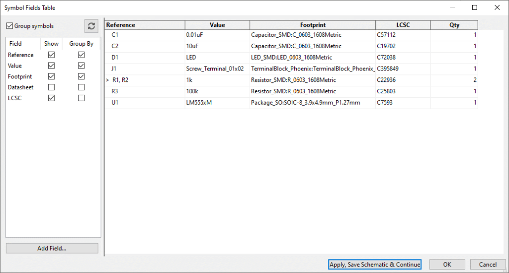
Firstly, add the LCSC Part Number column in Symbol Entry Field list. This is actually the vendor part number. To be able to know this number, you have to access JLCPCB’s parts library. Go ahead and click the Bulk Edit Fields of all Symbols in Schematic button above to continue.
The final Symbol Field list should look something similar to this:
Click Apply, Save Schematic & Continue and then press OK.
Output the BOM According to Specifications
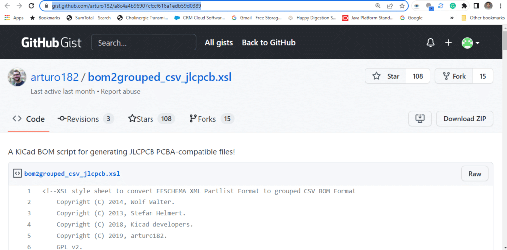
You can use a scripting tool to output your BOM according to your manufacturer’s specs. Go to Arturo’s BOM exporting script and download the zipped script file.
Then add this as a script you’ll use to generate your BOM. (Try not to have spaces or odd characters on your directory names to run the script without issues). Click Generate to continue.
Generating Pick and Place (Position or Centroid) files
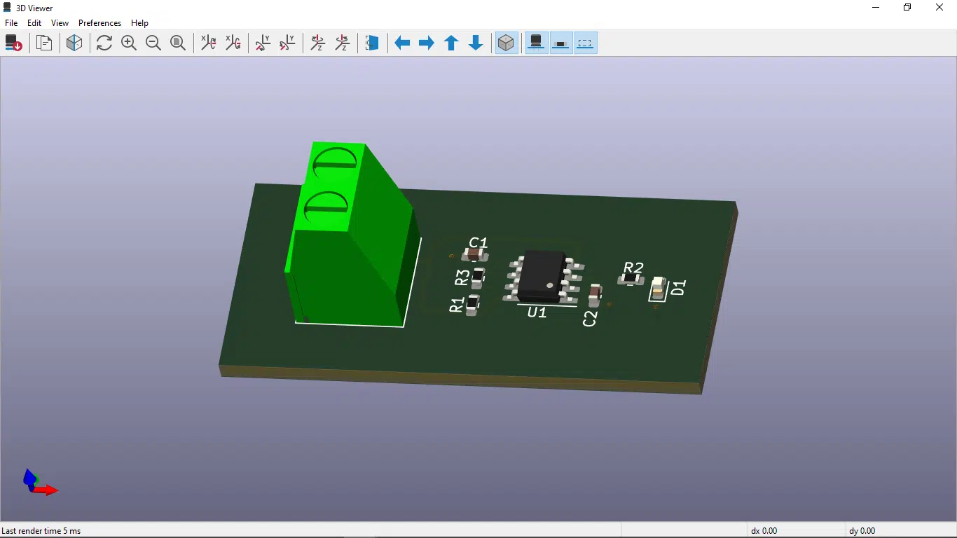
The last piece of files you need are the position or pick and place files for a machine to assemble your boards successfully. Position files are the X & Y position values of each component with respect to an origin. You’ll see these values when you click on the properties of your components in the KiCAD PCB Editor.
Click on File ->Fabrication Outputs -> Component Placement (.pos) to continue.
Since JLCPCB (or your manufacturer) has specific requirements for this position file you may need to edit the table.
Your on your Way to Getting your Boards Manufactured and Assembled
Remember the location of where you generated these BOM and pick and place files so that you can get them ready to be uploaded to your manufacturer’s file portal.