Read this article if you want more info regarding configuring, installing, and running I2C devices on your ESP32 using an I2C Driver in ESP-IDF.
Introduction
Previously, you’ve learned about device drivers and how they can be used to implement operating system-friendly devices. Additionally, in that blog, there was an example of how to use the UART driver. Now, you’ll learn how to use an I2C driver in ESP-IDF.
How to Use the I2C Peripheral
Like most other peripherals, the proper way to use the I2C peripheral to communicate efficiently with your device involves three steps:
- I2C Peripheral Configuration
- I2C Driver Installation
- I2C Peripheral Operation in your OS
A temperature sensor, TC74, will demonstrate the process involved in the listed steps. This is a Tiny Serial Digital Thermal Sensor from Microchip. It outputs a simple 8-bit digital word through the I2C bus.

Circuit Setup
Here is the circuit setup along with other additional components. This is similar to a custom ESP32 learning kit, only that it’s now wired for the newer ESP32-S3 DevKitC-1 version.

I2C Peripheral Configuration
Peripheral configuration starts in the init_i2c( ) function. Inside the function, you’ll see:
					void init_i2c(void)
{
    int i2c_master_port = I2C_MASTER_PORT;

    i2c_config_t conf = {
        .mode = I2C_MODE_MASTER,
        .sda_io_num = I2C_MASTER_SDA,
        .scl_io_num = I2C_MASTER_SCL,
        .sda_pullup_en = GPIO_PULLUP_DISABLE,
        .scl_pullup_en = GPIO_PULLUP_DISABLE,
        .master.clk_speed = I2C_MASTER_FREQ,
    };

    i2c_param_config(i2c_master_port, &conf);

    i2c_driver_install(i2c_master_port, conf.mode, 0, 0, 0);
}
A configuration structure conf of i2c_config_t sets all the I2C parameters you need before enabling your device. After that, these parameters are passed to the i2c_param_config( ) function, mostly HAL (Hardware Abstraction Layer) functions created for your peripheral.
I2c dRIVER iNSTALLATION
Before continuing to use your I2C peripheral, you must ensure that your Operating System (FreeRTOS, that is), allocates the needed resources to run this peripheral, as well as implement its operation in a thread-friendly manner. With this, you need to use i2c_driver_install( ). You’ll need to populate the parameters consisting of i2c_port_type, mode (master or slave), some buffer-related items (mostly used for slave reception), and special interrupt flags (if needed).
i2c_driver_install(i2c_master_port, conf.mode, 0, 0, 0);
I2C Peripheral Operation in your OS
Now that you’ve successfully set up your I2C peripheral, you can create tasks for it. Start by creating a task to read the TC74 config and address register. Browse the datasheet to know those registers and how they can be accessed. Incidentally, you can use pre-made functions from ESP-IDF’s driver/i2c.c source file for this. Otherwise, you may have to create your own I2C function commands using the command link feature of the ESP-IDF I2C driver. The commands inside these i2c functions are sent to a queue so that they can run without interruptions.
					void tc74_task(void *parameters)
{
    const uint8_t config_reg = TC74_CONFIG_REGISTER;
    const uint8_t temp_reg = TC74_READ_TEMP_REGISTER;

    const int i2c_master_port = I2C_MASTER_PORT;


    for(;;)
    {

        i2c_master_write_read_device(i2c_master_port, TC74_SENSOR_ADDR, &config_reg, 1, &data[0], 1, 1000/portTICK_PERIOD_MS);
        ESP_LOGI(TAG, "CONFIG = %X", data[0]);

        vTaskDelay(500/portTICK_PERIOD_MS);

        i2c_master_write_read_device(i2c_master_port, TC74_SENSOR_ADDR, &temp_reg, 1, data, 1, 1000/portTICK_PERIOD_MS);
        ESP_LOGI(TAG, "TEMP = %X", data[0]);
        ESP_LOGI(TAG, " ");

        vTaskDelay(500/portTICK_PERIOD_MS);
    }
}
You can create your task in main as follows:
xTaskCreate(tc74_task, "tc74", 1024*2, NULL, configMAX_PRIORITIES-1, NULL);
The Main code
Here is the main code you can use as a reference:
					#include <stdio.h>
#include <driver\i2c.h>
#include <freertos\FreeRTOS.h>
#include <freertos\task.h>
#include <esp_log.h>
#include <esp_task_wdt.h>

#define I2C_MASTER_NUM I2C_NUM_1
#define I2C_MASTER_SCL 1
#define I2C_MASTER_SDA 2

#define I2C_MASTER_PORT 1
#define I2C_MASTER_FREQ 100000

#define TC74_SENSOR_ADDR                    0x4D        /*!< Slave address of the MPU9250 sensor */
#define TC74_READ_TEMP_REGISTER             0x00        /*!< Register addresses of the temp register */
#define TC74_CONFIG_REGISTER                0x01        /*!< Register addresses of the config register */
#define TC74_DATA_READY_BIT                 6

const char *TAG = "TC74 Example I2C";


void init_i2c(void);

void tc74_task(void * parameters);

uint8_t data[2];


void app_main(void)
{
    init_i2c();

    xTaskCreate(tc74_task, "tc74", 1024*4, NULL, 1, NULL);

    vTaskDelay(100/portTICK_PERIOD_MS);

}

void init_i2c(void)
{
    int i2c_master_port = I2C_MASTER_PORT;

    i2c_config_t conf = {
        .mode = I2C_MODE_MASTER,
        .sda_io_num = I2C_MASTER_SDA,
        .scl_io_num = I2C_MASTER_SCL,
        .sda_pullup_en = GPIO_PULLUP_DISABLE,
        .scl_pullup_en = GPIO_PULLUP_DISABLE,
        .master.clk_speed = I2C_MASTER_FREQ,
    };

    i2c_param_config(i2c_master_port, &conf);

    i2c_driver_install(i2c_master_port, conf.mode, 0, 0, 0);
}


void tc74_task(void *parameters)
{
    const uint8_t config_reg = TC74_CONFIG_REGISTER;
    const uint8_t temp_reg = TC74_READ_TEMP_REGISTER;

    const int i2c_master_port = I2C_MASTER_PORT;

    esp_err_t ret;

    for(;;)
    {

        ret = i2c_master_write_read_device(i2c_master_port, TC74_SENSOR_ADDR, &config_reg, 1, &data[0], 1, 1000/portTICK_PERIOD_MS);
        if(ret == ESP_OK){
            ESP_LOGI(TAG, "CONFIG = %X", data[0]);
        }else{
            ESP_LOGI(TAG, "Error");
        }

        vTaskDelay(100/portTICK_PERIOD_MS);

        ret = i2c_master_write_read_device(i2c_master_port, TC74_SENSOR_ADDR, &temp_reg, 1, data, 1, 1000/portTICK_PERIOD_MS);
        if(ret == ESP_OK){
            ESP_LOGI(TAG, "TEMP = %X", data[0]);
        }else{
            ESP_LOGI(TAG, "Error");
        }

        ESP_LOGI(TAG, " ");

        vTaskDelay(1000/portTICK_PERIOD_MS);
    }
}
Additional Coding
Now that you’ve gone this far in creating your I2C task, why not test out other tasks running along with it? Below is the code for a blinky LED strip task running with your I2C task. This should be similar to our previous blog on multitasking and GPIO ports, only that it’s now wired for the newer ESP32-S3 DevKitC-1 version.
					#include <stdio.h>
#include <driver\i2c.h>
#include <freertos\FreeRTOS.h>
#include <freertos\task.h>
#include <esp_log.h>

#define I2C_MASTER_NUM I2C_NUM_1
#define I2C_MASTER_SCL 1
#define I2C_MASTER_SDA 2

#define I2C_MASTER_PORT 1
#define I2C_MASTER_FREQ 100000

#define TC74_SENSOR_ADDR                    0x4D        /*!< Slave address of the MPU9250 sensor */
#define TC74_READ_TEMP_REGISTER             0x00        /*!< Register addresses of the temp register */
#define TC74_CONFIG_REGISTER                0x01        /*!< Register addresses of the config register */
#define TC74_DATA_READY_BIT                 6

const char *TAG = "TC74 Example I2C";

// LED strip ports
#define LED_STRIP1_G GPIO_NUM_4
#define LED_STRIP1_R GPIO_NUM_5
#define LED_STRIP1_B GPIO_NUM_6

#define LED_STRIP2_G GPIO_NUM_17
#define LED_STRIP2_R GPIO_NUM_18
#define LED_STRIP2_B GPIO_NUM_8

#define LED_STRIP3_G GPIO_NUM_10
#define LED_STRIP3_R GPIO_NUM_11
#define LED_STRIP3_B GPIO_NUM_12

#define LED_STRIP1_BIT_MASK (1ULL << LED_STRIP1_G | 1ULL << LED_STRIP1_R | 1ULL << LED_STRIP1_B)
#define LED_STRIP2_BIT_MASK (1ULL << LED_STRIP2_G | 1ULL << LED_STRIP2_R | 1ULL << LED_STRIP2_B)
#define LED_STRIP3_BIT_MASK (1ULL << LED_STRIP3_G | 1ULL << LED_STRIP3_R | 1ULL << LED_STRIP3_B)

// Push Buttons
#define PUSH_BUTTON_1 GPIO_NUM_7
#define PUSH_BUTTON_2 GPIO_NUM_9
#define PUSH_BUTTON_3 GPIO_NUM_13

#define PUSH_BUTTON_1_BIT_MASK (1ULL << PUSH_BUTTON_1)
#define PUSH_BUTTON_2_BIT_MASK (1ULL << PUSH_BUTTON_2)
#define PUSH_BUTTON_3_BIT_MASK (1ULL << PUSH_BUTTON_3)


gpio_config_t myGPIOconfig;


void init_i2c(void);
void init_gpio(void);

static void led_strip_task(void * parameters);
static void tc74_task(void * parameters);

uint8_t data[2];


void app_main(void)
{
    init_i2c();

    init_gpio();

    xTaskCreate(led_strip_task, "led_strip", 1024*2, NULL, configMAX_PRIORITIES, NULL);
    xTaskCreate(tc74_task, "tc74", 1024*2, NULL, configMAX_PRIORITIES-1, NULL);


}

void init_i2c(void)
{
    int i2c_master_port = I2C_MASTER_PORT;

    i2c_config_t conf = {
        .mode = I2C_MODE_MASTER,
        .sda_io_num = I2C_MASTER_SDA,
        .scl_io_num = I2C_MASTER_SCL,
        .sda_pullup_en = GPIO_PULLUP_DISABLE,
        .scl_pullup_en = GPIO_PULLUP_DISABLE,
        .master.clk_speed = I2C_MASTER_FREQ,
    };

    i2c_param_config(i2c_master_port, &conf);

    i2c_driver_install(i2c_master_port, conf.mode, 0, 0, 0);
}

void init_gpio(void)
{
    // Configure Digital I/O for LEDs
    myGPIOconfig.pin_bit_mask = (LED_STRIP1_BIT_MASK | LED_STRIP2_BIT_MASK | LED_STRIP3_BIT_MASK);
    myGPIOconfig.pull_down_en = GPIO_PULLDOWN_DISABLE;
    myGPIOconfig.pull_up_en = GPIO_PULLUP_DISABLE;
    myGPIOconfig.mode = GPIO_MODE_OUTPUT;
    myGPIOconfig.intr_type = GPIO_INTR_DISABLE;

    gpio_config(&myGPIOconfig);

    myGPIOconfig.pin_bit_mask = (PUSH_BUTTON_2_BIT_MASK | PUSH_BUTTON_3_BIT_MASK);
    myGPIOconfig.pull_down_en = GPIO_PULLDOWN_DISABLE;
    myGPIOconfig.pull_up_en = GPIO_PULLUP_DISABLE;
    myGPIOconfig.mode = GPIO_MODE_INPUT;
    myGPIOconfig.intr_type = GPIO_INTR_DISABLE;

    gpio_config(&myGPIOconfig);

    gpio_set_direction(PUSH_BUTTON_1, GPIO_MODE_INPUT);
    gpio_set_pull_mode(PUSH_BUTTON_1, GPIO_PULLUP_ONLY);

}

void led_strip_task(void *parameters)
{
    for(;;)
    {
        gpio_set_level(LED_STRIP1_G, 1);
        vTaskDelay(100/portTICK_PERIOD_MS);
        gpio_set_level(LED_STRIP1_G, 0);

        gpio_set_level(LED_STRIP1_R, 1);
        vTaskDelay(100/portTICK_PERIOD_MS);
        gpio_set_level(LED_STRIP1_R, 0);

        gpio_set_level(LED_STRIP1_B, 1);
        vTaskDelay(100/portTICK_PERIOD_MS);
        gpio_set_level(LED_STRIP1_B, 0);
        vTaskDelay(100/portTICK_PERIOD_MS);

    }
}

void tc74_task(void *parameters)
{
    const uint8_t config_reg = TC74_CONFIG_REGISTER;
    const uint8_t temp_reg = TC74_READ_TEMP_REGISTER;

    const int i2c_master_port = I2C_MASTER_PORT;


    for(;;)
    {

        // Use the I2C Device
        i2c_master_write_read_device(i2c_master_port, TC74_SENSOR_ADDR, &config_reg, 1, &data[0], 1, 100/portTICK_PERIOD_MS);
        ESP_LOGI(TAG, "CONFIG = %X", data[0]);

        vTaskDelay(500/portTICK_PERIOD_MS);

        i2c_master_write_read_device(i2c_master_port, TC74_SENSOR_ADDR, &temp_reg, 1, data, 1, 100/portTICK_PERIOD_MS);
        ESP_LOGI(TAG, "TEMP = %X", data[0]);
        ESP_LOGI(TAG, " ");

        vTaskDelay(500/portTICK_PERIOD_MS);
    }
}
Circuit in Action
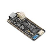
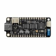
SHOP THIS PROJECT
-
Sale!

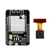
ESP32-CAM WiFi Bluethooth Development Board with OV2640 Camera Module
$31.95Original price was: $31.95.$29.95Current price is: $29.95. Add to cart